Software rasterizer
| Links:

In this project, I wrote a software rasterizer for polygonal meshes. Essentially, this involved:
- Loading a .obj polygonal mesh.
- Triangulate each polygonal face.
- For each triangle:
- Transform its vertices to camera space, project them to screen space, divide them by their z-coordinate to perform perspective diminishing, and then transform them from NDC coordinates to pixel coordinates.
- Cull it if it lies completely behind the near plane or beyond the far plane of the camera.
- Compute its axis-aligned bounding box in pixel space, clamped to the extents of the image.
- For each pixel row contained by the bounding box:
- Determine the interval of pixels in the row that the triangle overlaps.
- For each pixel in this interval (a triangle fragment):
- Compute its barycentric coordinates in relation to the triangle’s vertices in pixel space.
- Use these barycentric coordinates to compute the fragment’s z-coordinate in a perspective-correct way.
- Perform the depth test and update the z-buffer.
- Use the barycentric coordinates to interpolate vertex attributes in a perspective-correct way in pixel space. Vertex attributes include normal and texture UV coordinate.
- Perform back-face culling of the triangle based on the orientation of the interpolated normal with repect to the camera.
- Evaluate a reflection model (Lambertian diffuse reflection) to obtain the fragment’s color. The camera acts as a flashlight; Lambert’s cosine law can be evaluated with the interpolated normal in pixel space and the light vector in camera space.
Because of the distortion that results from a perspective projection, we can’t simply use the barycentric coordinates of the fragment in pixel space to interpolate vertex normals and UVs. The method to perform perspective-correct interpolation that I implemented here is explained in Rasterization: a Practical Implementation.
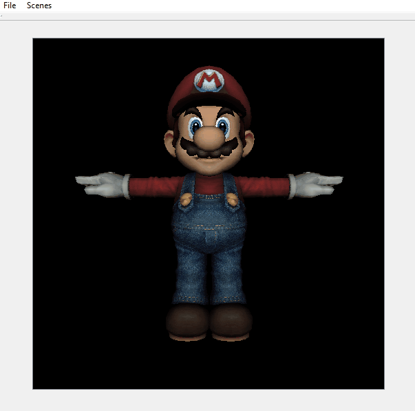
An additional feature that I decided to implement was normal mapping. This involved computing a tangent-bitangent-normal frame of reference for tangent space with respect to world space out of world-space vertex positions and UVs. The inverse of the corresponding homogeneous matrix can then be used to transform the world-space light vector to tangent space to compute Lambert’s cosine law term with a tangent-space normal read from a normal map.
| Without normal mapping | With normal mapping |
|---|---|
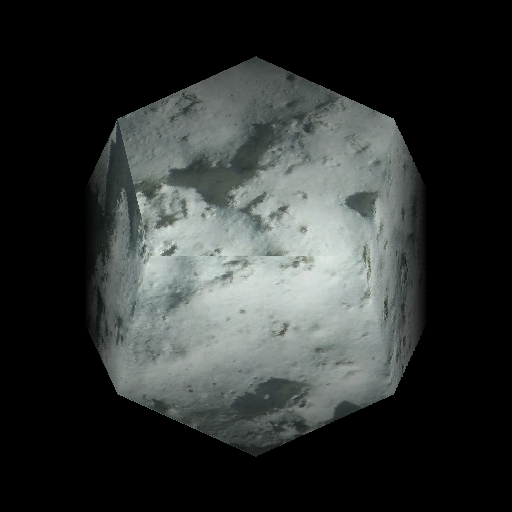 | 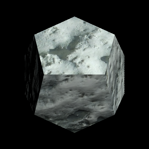 |
 | 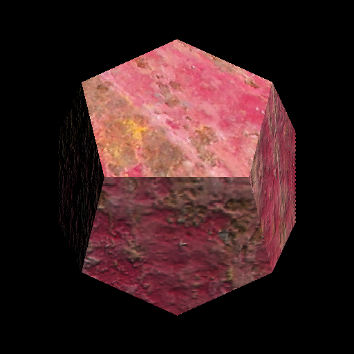 |
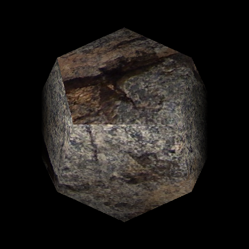 | 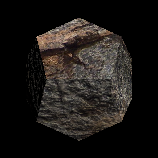 |