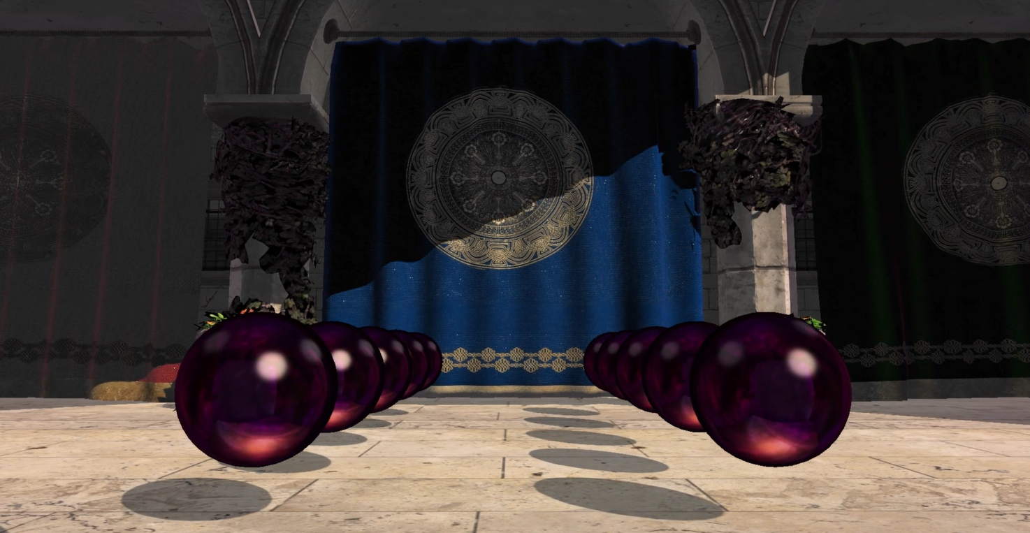
Shadow mapping
| Links: Github repo

I implemented the standard shadow mapping technique back in 2022 using a simple scene found in the book Introduction to 3D Game Programming with DirectX 12. Now that I wrote a glTF loader for CDX, I’m adjusting existing code to make it work for bigger and more complex scenes. This video shows shadows produced by this technique on the Sponza scene; it looks far from perfect at the moment, but I’m working on it.
Overview
The basic shadow mapping algorithm renders the scene depth to a texture (i.e. the shadow map) from the viewpoint of the light source. The resulting rendered fragments cannot be in shadow because they have a nonoccluded line of sight with the light source. The shadow map will thus contain the depth values of all the visible fragments from the perspective of the light.
The shadow mapping algorithm does 2 render passes: 1) a shadow pass that renders the scene depth from the viewpoint of the light into the shadow map; and 2) a main pass that renders the scene as usual to the back buffer from the viewpoint of the camera, using the shadow map in the shader.
Rendering the shadow map: the shadow pass
The shadow map is really a depth/stencil buffer, so we take advantage of the built-in depth buffer creation of the hardware graphics pipeline. Since we let the hardware do it, we don’t need CPU access to it, so a default heap (D3D12_HEAP_TYPE_DEFAULT) instead of an upload heap is where we create the shadow map’s resource.D3D12_RESOURCE_DESC resourceDesc;
ZeroMemory(&resourceDesc, sizeof(D3D12_RESOURCE_DESC));
resourceDesc.Dimension = D3D12_RESOURCE_DIMENSION_TEXTURE2D;
resourceDesc.Alignment = 0;
resourceDesc.Width = 2048;
resourceDesc.Height = 2048;
resourceDesc.DepthOrArraySize = 1;
resourceDesc.MipLevels = 1;
resourceDesc.Format = DXGI_FORMAT_R24G8_TYPELESS;
resourceDesc.SampleDesc.Count = 1;
resourceDesc.SampleDesc.Quality = 0;
resourceDesc.Layout = D3D12_TEXTURE_LAYOUT_UNKNOWN;
resourceDesc.Flags = D3D12_RESOURCE_FLAG_ALLOW_DEPTH_STENCIL;
D3D12_CLEAR_VALUE clearValue;
clearValue.Format = DXGI_FORMAT_D24_UNORM_S8_UINT;
clearValue.DepthStencil.Depth = 1.0;
clearValue.DepthStencil.Stencil = 0;
Microsoft::WRL::ComPtr<ID3D12Resource> resource;
CD3DX12_HEAP_PROPERTIES heapProperties = CD3DX12_HEAP_PROPERTIES(D3D12_HEAP_TYPE_DEFAULT);
device->CreateCommittedResource(
&heapProperties,
D3D12_HEAP_FLAG_NONE,
&resourceDesc,
D3D12_RESOURCE_STATE_GENERIC_READ,
&clearValue,
IID_PPV_ARGS(&resource)
);
Observe that \(Dimension = D3D12\_RESOURCE\_DIMENSION\_TEXTURE2D\): after creating the depth buffer from the perspective of the light source in the shadow pass, we’ll bind the resource to the pipeline as a \(Texture2D\) that the shader will then sample in the main pass; this texture will, of course, contain depth values and, as I’ll explain later, we don’t sample a depth texture in the way we do a color texture; that’s the reason why we don’t create a mipmap chain for this resource and instead set \(MipLevels = 1\). As for the dimensions of the resource, they determine the resolution of the shadow map, so the larger it is, the higher quality it’ll be; I used a resolution of 2048x2048.
Now, since the shadow map gets created in the shadow pass, we bind the resource to the pipeline as a depth-stencil buffer during that stage. Thus, we need a depth-stencil view for it:CD3DX12_CPU_DESCRIPTOR_HANDLE cpuDsvHandle
D3D12_DEPTH_STENCIL_VIEW_DESC dsvDesc = {};
dsvDesc.Format = DXGI_FORMAT_D24_UNORM_S8_UINT;
dsvDesc.ViewDimension = D3D12_DSV_DIMENSION_TEXTURE2D;
dsvDesc.Flags = D3D12_DSV_FLAG_NONE;
dsvDesc.Texture2D.MipSlice = 0;
device->CreateDepthStencilView(resource.Get(), &dsvDesc, cpuDsvHandle);
And since we sample the resulting shadow map in the main pass, we bind the resource as a texture during that stage, for which we need a shader resource view for it:CD3DX12_CPU_DESCRIPTOR_HANDLE cpuSrvHandle;
D3D12_SHADER_RESOURCE_VIEW_DESC srvDesc = {};
srvDesc.Format = DXGI_FORMAT_R24_UNORM_X8_TYPELESS;
srvDesc.Shader4ComponentMapping = D3D12_DEFAULT_SHADER_4_COMPONENT_MAPPING;
srvDesc.ViewDimension = D3D12_SRV_DIMENSION_TEXTURE2D;
srvDesc.Texture2D.MostDetailedMip = 0;
srvDesc.Texture2D.MipLevels = 1;
srvDesc.Texture2D.ResourceMinLODClamp = 0.0f;
srvDesc.Texture2D.PlaneSlice = 0;
device->CreateShaderResourceView(resource.Get(), &srvDesc, cpuSrvHandle);
Rendering the scene’s depth from the perspective of a light source is not that different from doing it from the camera: we need a view matrix that transforms points from world space to light space and a projection matrix that defines the volume of emitted light: a frustum volume defined by a perspective projection can model spotlight volumes; a box volume defined by an orthographic projection can model bounded parallel light volumes; and a volume large enough to cover the entire scene can model the sun’s volume.
In my first scene, I used a bounded parallel light, so I modeled its volume using an orthographic projection. With orthographic projections, the viewing volume is a box that is axis-aligned with the view space basis vectors, with width \(w\) and height \(h\) that depend on the chosen resolution of the shadow map, a near plane \(n\), and a far plane \(f\) that looks down the positive \(z\)-axis of view space.
The view space orthographic view volume (the axis-aligned box) is subject to the following mapping: \[[-\frac{w}{2},\frac{w}{2}]\times[-\frac{h}{2},\frac{h}{2}]\times[n,f]\rightarrow[-1,1]\times[-1,1]\times[0,1]\]
Observe that this mapping rescales the width, height, and depth of the box to dimensions \([-1,1]\times[-1,1]\times[0,1]\), while also translating the near and far planes along the \(z\)-axis down to \(z=0\) and \(z=1\), respectively. To understand what a mapping does to any one vector, one often observes what it does to a few reference vectors; usually those are the vector space’s basis vectors, but in this case we’ll use the endpoints of the intervals that define the view volume. For the \(x\) and \(y\) coordinates of a point in view space, the relation is as follows: \[\begin{aligned} \frac{2}{w}\cdot[-\frac{w}{2},\frac{w}{2}] &= [-1,1] \Longrightarrow x \rightarrow \frac{2}{w}\cdot x \\ \frac{2}{h}\cdot[-\frac{h}{2},\frac{h}{2}] &= [-1,1] \Longrightarrow y \rightarrow \frac{2}{h}\cdot y \end{aligned}\]
which indicates that the mapping scales their value by a factor of \(\frac{2}{w}\) and \(\frac{2}{h}\), respectively. The mapping for \(z\) corresponds to a scaling (from a range of size \(f-n\) to one of size \(1\)) and a translation (one such that \(n\) is taken to \(0\) and \(f\) to \(1\)), so it’s reasonable to think that the \(z\) coordinate is subject to a linear mapping of the form \(g(z)=az+b\), where \(a\) scales the coordinate and \(b\) translates it. Now, recall that the mapping takes \(n\) to \(0\) and \(f\) to \(1\)$; thus, \(g(n)=0\) and \(g(f)=1\). We may use these conditions to obtain \(a\) and \(b\), by solving the following system of 2 equations in 2 variables: \[\begin{aligned} an+b &= 0 \\ af+b &= 1 \\ &\Longrightarrow \\ a &= \frac{1}{f-n} \\ b &= -\frac{n}{f-n} \end{aligned}\]
Therefore, the orthographic mapping \(T\) of view space to projection space of a point \((x,y,z)\) in view space is given by \[\begin{aligned} T: x'=\frac{2}{w}\cdot x,\text{ }y'=\frac{2}{h}\cdot y,\text{ }z'=g(z)=\frac{z-n}{f-n} \end{aligned}\]
with matrix form \[\begin{pmatrix}x'\\y'\\z'\\1\end{pmatrix}=\begin{pmatrix}\frac{2}{w}&0&0&0\\0&\frac{2}{h}&0&0\\0&0&\frac{1}{f-n}&0\\0&0&\frac{n}{f-n}&1\end{pmatrix}\begin{pmatrix}x\\y\\z\\1\end{pmatrix}=\begin{pmatrix}\frac{2}{w}x\\\frac{2}{h}y\\\frac{z-f}{f-n}\\1\end{pmatrix}\]
After transforming a point in view space with the orthographic projection matrix, the point will be in NDC space. This mapping preserves parallel lines and doesn’t cause foreshortening of objects as points recede into the distance, unlike the perspective projection, which makes parallel lines meet at a single vanishing point that creates this effect. In addition to that, the mapping preserves the relative depth of points, which is an extremely desirable property.
In DirectX 12, an orthographic projection matrix can be obtained by supplying a description of the orthographic view volume to \(\text{DirectX::XMMatrixOrthographicOffCenterLH}\). Assuming that \(\text{XMFLOAT3 parallelLightPosition}\) is the position of a parallel light that points towards the origin of world space, the following code snippet assembles a view matrix for the vector space of that light source (i.e. light space) and an orthographic projection matrix:XMVECTOR targetPosition = DirectX::XMVectorSet(0.0f, 0.0f, 0.0f, 0.0f);
XMVECTOR lightUpVector = DirectX::XMVectorSet(0.0f, 1.0f, 0.0f, 0.0f);
XMMATRIX lightViewMatrix = DirectX::XMMatrixLookAtLH(parallelLightPosition, targetPosition, lightUpVector);
XMFLOAT3 lightSpaceWorldOrigin;
DirectX::XMStoreFloat3(&lightSpaceWorldOrigin, DirectX::XMVector3TransformCoord(targetPosition, lightViewMatrix));
float sceneBoundsRadius = sqrtf(10.0f * 10.0f + 15.0f * 15.0f);
// Orthographic view volume: [left,right]x[bottom,top]x[near,far].
float l = lightSpaceWorldOrigin.x - sceneBoundsRadius;
float r = lightSpaceWorldOrigin.x + sceneBoundsRadius;
float b = lightSpaceWorldOrigin.y - sceneBoundsRadius;
float t = lightSpaceWorldOrigin.y + sceneBoundsRadius;
float n = lightSpaceWorldOrigin.z - sceneBoundsRadius;
float f = lightSpaceWorldOrigin.z + sceneBoundsRadius;
// Orthographic projection matrix.
XMMATRIX lightProjectionMatrix = DirectX::XMMatrixOrthographicOffCenterLH(l, r, b, t, n, f);
With the view and projection matrices in hand, the shadow pass concludes with the series of draw calls that renders the scene; interestingly enough, this series of draw calls is the same that will be executed in the main pass, just with a different set of transformation matrices, a different pipeline configuration, and different vertex and pixel shaders. The shader code for rendering the shadow map is actually pretty simple: the vertex shader just transforms the scene’s vertices to light space and then to NDC space using the corresponding view matrix and the orthographic projection matrix; and the pixel shader doesn’t need to do anything: the non-programmable pixel merging stage that follows pixel shading will populate the depth buffer (i.e. the shadow map) automatically using the \(z\)-buffer algorithm.
A couple of details are noteworthy in the setup of the shadow pass’s PSO. The first one is that \(NumRenderTargets = 0\), which, in effect, disables writes to a color buffer during the pixel shading and merging stages; we don’t need one. The other one is the rasterizer state; \(DepthBias\), \(DepthBiasClamp\), and \(SlopeScaledDepthBias\) exist because modern hardware graphics pipelines have intrinsic support for depth biasing, a critical operation we’ll employ later in the main pass.D3D12_GRAPHICS_PIPELINE_STATE_DESC psoDesc;
psoDesc.InputLayout = ...;
psoDesc.pRootSignature = ...;
psoDesc.VS = ...;
psoDesc.PS = ...;
psoDesc.RasterizerState = CD3DX12_RASTERIZER_DESC(D3D12_DEFAULT);
psoDesc.RasterizerState.DepthBias = 100000;
psoDesc.RasterizerState.DepthBiasClamp = 0.0f;
psoDesc.RasterizerState.SlopeScaledDepthBias = 1.0f;
psoDesc.BlendState = CD3DX12_BLEND_DESC(D3D12_DEFAULT);
psoDesc.DepthStencilState = CD3DX12_DEPTH_STENCIL_DESC(D3D12_DEFAULT);
psoDesc.SampleMask = UINT_MAX;
psoDesc.PrimitiveTopologyType = D3D12_PRIMITIVE_TOPOLOGY_TYPE_TRIANGLE;
psoDesc.RTVFormats[0] = DXGI_FORMAT_UNKNOWN;
psoDesc.NumRenderTargets = 0;
psoDesc.DSVFormat = DXGI_FORMAT_D24_UNORM_S8_UINT;
Microsoft::WRL::ComPtr<ID3D12PipelineState> pso;
device->CreateGraphicsPipelineState(&psoDesc, IID_PPV_ARGS(&pso));
Using the shadow map: the main pass
…
